

In my last post, I referenced a temperature collector app that we implemented in Flask. The purpose of the app is to understand how well the heating and air conditioning work throughout the house. While my existing Flask app and iOS Shortcuts work to collect temperature data, the inability to reliably schedule the Shortcut led me to look for an autonomous, low-power solution: the Raspberry Pico W with a DHT11 temperature sensor.
The Wiring
The wiring is very simple. The device includes:
- A temperature sensor,
- Indicator LEDs
- DIP switch to select a room
- A circuit to measure the battery level
Temperature Sensor: DHT11
For the temperature sensor, we will be using a DHT11. The accuracy is not great, it is +/- 2 degrees celsius. DHT22 would be better, because it has an accuracy of +/- 0.5 degrees celsius. I tested the DHT22, but these require 5V, so I decided to stick with the DHT11, which only requires 3V (and is what I already had). Throughout my development, I also learned that the sensor acclimates slowly to the temperature after powering up. Therefore, we need to add a slight delay when it is first powered up. Over the recording timeline, this is usually not a concern, and the accuracy does not seem to be impacted by deep sleep. Although the version of DHT11 that we will use has 4 pins, we only need to use 3: Vcc, data, and ground.
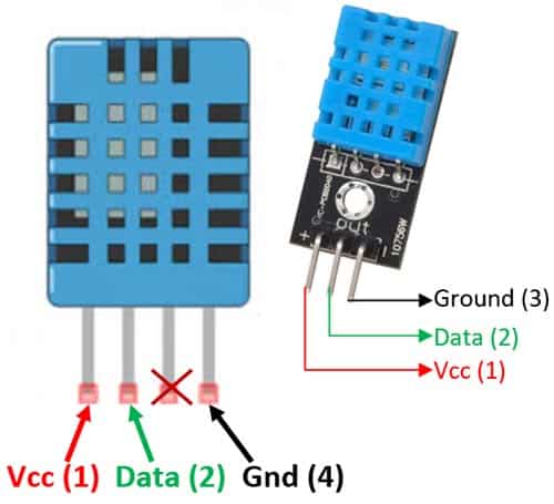
Source https://components101.com/sensors/dht11-temperature-sensor
DHT11 accepts input voltage between 3V and 5V. Since we are using the Raspberry Pico, we can power from the 3v3 pin (pin 36).
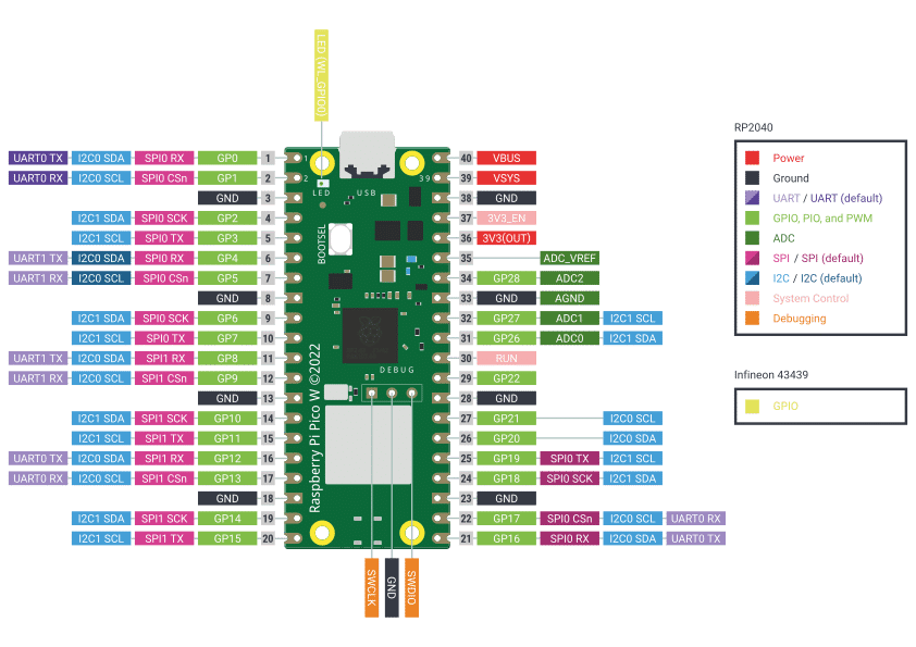
Source https://www.raspberrypi.com/documentation/microcontrollers/pico-series.html
We can connect the data pin to any GPIO pin. In our case, we are connecting to GPIO4 (pin 6). Ground can be connected to any of the Raspberry Pico ground pins.
Indicator LEDs
I wanted to be able to see when the device is working, so I added two indicator LEDs. One shows when the sensor is awake (in my case red), and the other shows when the sensor is transmitting data (green). These are fairly straightforward, each using a 330 ohm resistor and connected to pins 15 and 16 (respectively). As a side note, I explored using one resistor for both, but discovered that this is a bad idea since the current does not divide evenly between the two LEDs (and resistors are really inexpensive, currently about $0.10/resistor).
DIP Switch
I also wanted the capability of changing rooms without connecting the device to a computer and updating the code. Therefore, I added a DIP switch with 4 switches. This allows up to 2^4 or 16 rooms. These are connected to pins 10, 11, 12, and 13.
Battery Level
In addition to the temperature sensor, I also want to keep track of the battery. Since I am going to place this in a room and run it for some period of time, I need to know when the battery needs to be replaced.
Battery voltage monitoring is handled through an ADC on pin 26, with a voltage divider (two 100k resistors) to bring the battery voltage into the safe 0-3.3V range for the Pico.
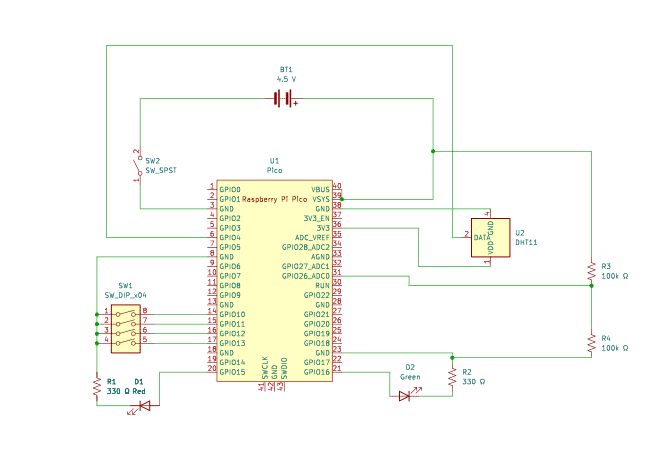
The Final Schematic
Here is the schematic of the final wiring.
The Code
Next, we will move on to the code. We will create three modules:
- main.py: starts the device
- temperature.py: handles collection of temperature and humidity
- daemon.py: main loop that initiates the temperature collection and sends it to the server
Main.py
The main code is very straightforward. MicroPython on the Pico looks for main.py when it starts. Our code just calls the run_daemon function in daemon.py.
import daemon

daemon.run_daemon()Temperature.py
Temperature.py contains a class with two methods:
- Init: Initializes the dht11 sensor
- Get_temperature: gets the temperature from the sensor
import machine
from machine import Pin
import dht
from time import sleep

pin_num = 4

class Temperature:
    def __init__(self):
        self.sensor_pin = Pin(pin_num, Pin.IN, Pin.PULL_UP)
        self.sensor = dht.DHT11(self.sensor_pin)

    def get_temperature(self):
        self.sensor.measure()

        # The temperature from DHT11 is in celcius, convert to farenheit
        temp = self.sensor.temperature() * (9/5) + 32.0
        humidity = self.sensor.humidity()

return {"temperature": temp, "humidity":humidity}MicroPython has a built in module (dht) to handle both DHT11 and DHT22. In the initialization, we set up the GPIO pin with a pullup resistor and then create a variable called sensor to hold the class instance. Whenever we call get_temperature, we simply need to call sensor.measure() and then retrieve the temperature and humidity.
Daemon.py
The daemon module handles the heavy lifting of reading temperature sensors, managing WiFi connections, and posting data to our Flask server. This module runs continuously on each Pico W device stationed around the house, waking up periodically to take measurements and log them to our server.
What is a daemon?
Before diving into the code, it’s worth explaining the term “daemon” itself. In computer science, a daemon refers to a program that operates as a background process without direct user interaction. While you might see it spelled “demon,” the classical “daemon” spelling reflects its roots in Greek mythology, where a daemon was a helpful spirit working behind the scenes. In Unix-like systems, daemons typically handle tasks like web servers, email handlers, and system logging. Our temperature collector doesn’t run on Unix, but it embodies the same concept—a background process that runs autonomously, performing its assigned task without requiring someone to manually trigger it each time.
What Does the Daemon Do?
At its core, the daemon performs a simple cycle: connect to WiFi, read the temperature and humidity from the sensor, determine the location of the sensor based on the DIP switch settings, and POST that data to our Temperature Collector server. After successfully logging the data, it goes into deep sleep mode to conserve battery power. The device wakes up an hour later to repeat the process.
The daemon logs any errors locally to the Pico’s filesystem, which helps with debugging. Since our device does not have a screen, it can be frustrating when the server doesn’t receive a POST or if one of the LEDs stays lit when the device should have gone to sleep.
Room Configuration with DIP Switches
One of the trickier design decisions was figuring out how each sensor knows which room it’s in. I could have hardcoded the location into each device, but that would require reflashing the firmware every time I moved a sensor. Instead, I used a 4-position DIP switch to configure the room assignment.
The get_room_name() function reads the DIP switch state on pins 10-13 and maps the binary value to room names. Position 0 is the basement, position 1 is the loft, and so on. This gives us up to 16 different room configurations without touching the code. When I move a sensor, I just flip the DIP switches and restart it.
Power Management
Since some of these sensors run on battery power, battery conservation is critical. The daemon uses the Pico W’s deep sleep functionality to shut down almost completely between readings. The deep_sleep() function puts the device into a low-power state where it draws minimal current, then automatically wakes after the specified interval.
MicroPython on the Pico W has a few quirks, particularly around WiFi management and deep sleep behavior. The key was adding proper delays and cleanup steps, like deinitializing the WiFi interface before entering deep sleep. Otherwise, the device will still pull higher current.
The daemon also detects whether it’s running on USB power or battery by checking the VBUS pin. When connected to USB (such as during development), it skips the deep sleep and simply uses time.sleep() (also called light sleep) between cycles. This makes debugging much easier since the device doesn’t completely reset between readings.
The daemon includes this battery voltage in the data payload when running on battery power, which lets us monitor battery health over time.
Error Handling and Feedback
The daemon includes several mechanisms to handle failures gracefully. If the WiFi connection fails after 20 attempts, it logs the error to a local file and goes back to sleep rather than burning battery trying endlessly to connect. Any exceptions during the temperature logging process are also caught and written to the error log.
Visual feedback is provided through two LEDs. Pin 15 controls a status LED that turns on during the active logging cycle, while pin 16 controls a “success” LED that blinks three times after successfully posting data to the server. This makes it easy to verify at a glance that sensors are working properly.
The Main Loop
The run_daemon() function ties everything together. After giving the temperature sensor five seconds to initialize (as noted above the DHT sensor seems to need to acclimate when initiated), it enters an infinite loop: turn on the status LED, connect to WiFi, log the temperature data, turn off the LED, and go to sleep. The cycle repeats every hour (3600 seconds), though this interval is configurable.
The Full Daemon Code
# Daemon process for temperature collection
# Runs every x minutes to log temperature data (sending to TempCollector API)
import network
import secrets
import time
import urequests
from temperature import Temperature
import machine
import time
import ujson

DEVICE_ID = 'pico_temp_001'

def strftime(t):
    '''Format a time tuple into a string.'''
    return "{:04}-{:02}-{:02} {:02}:{:02}:{:02}".format(t[0], t[1], t[2], t[3], t[4], t[5])

def get_room_name():
    '''Return the name of the room based on the DIP switch settings.'''
    dip_pins = [machine.Pin(i, machine.Pin.IN, machine.Pin.PULL_UP) for i in range(10, 14)]

    room_selection = 0
    for i, pin in enumerate(dip_pins):
        room_selection |= (not pin.value()) << i  # Active low

    print(f'DIP switch room selection: {room_selection}')

    if room_selection == 0:
        room_name = 'basement'
    elif room_selection == 1:
        room_name = 'loft'
    elif room_selection == 2:
        room_name = 'primary_bedroom'
    elif room_selection == 3:
        room_name = 'primary_bath'
    elif room_selection == 4:
        room_name = 'living_room'
    elif room_selection == 5:
        room_name = 'dining_room'
    else:
        room_name = 'other_'+room_selection

    return room_name

def connect_to_wifi():
    wlan = network.WLAN(network.STA_IF)
    wlan.active(True)
    wlan.connect(secrets.SSID, secrets.PASSWORD)

    max_attempts = 20
    attempts = 0
    while not wlan.isconnected() and attempts < max_attempts:
        print(f"Connect to WiFi (attempt {attempts + 1}/{max_attempts})")
        time.sleep(1)
        attempts += 1

    if wlan.isconnected():
        print('Connected to WiFi!')
        print('Network config:', wlan.ifconfig())
    else:
        print(strftime(time.localtime()), 'Failed to connect to WiFi')

    return wlan

def deep_sleep(seconds):
    print(f"Going to deep sleep for {seconds} seconds...")

    # Shut down the wifi
    wlan = network.WLAN(network.STA_IF)
    wlan.deinit()
    time.sleep(1)  # Give some time for messages to be printed

    machine.deepsleep(seconds * 1000)

def read_battery_voltage():
    adc = machine.ADC(26)  # Assuming Pin 31 is used for battery voltage reading
    raw_value = adc.read_u16()
    return raw_value

def convert_raw_to_voltage(raw_value):
    # R1 = 100k, R2 = 100k
    # Divider ratio is (R1+R2)/R2 = 2.0
    DIVIDER_RATIO = 2.0
    VOLTS_PER_BIT = 3.3 / 65535.0

    # Convert to the voltage at the ADC pin
    adc_voltage = raw_value * VOLTS_PER_BIT

    # Convert to the full battery voltage
    battery_voltage = adc_voltage * DIVIDER_RATIO
    return battery_voltage

def blinker():
    led = machine.Pin(16, machine.Pin.OUT)

    for _ in range(3):
        led.value(True)
        time.sleep(0.1)
        led.value(False)
        time.sleep(0.1)

def log_temperature(battery:bool):
    try:
        temp = Temperature()
        temperature_data = temp.get_temperature()


        url = 'http://192.168.1.201/temperature/record'
        headers = {"Content-Type": "application/json"}
        data = {
            'device_id': DEVICE_ID,
            'location': get_room_name(),
            'temperature': temperature_data['temperature'],
            'humidity': temperature_data['humidity'],
            'timestamp': strftime(time.localtime())
        }

        if (battery):
            battery = convert_raw_to_voltage(read_battery_voltage())
            data['battery'] = battery

        payload = ujson.dumps({'data': ujson.dumps(data)})

        print('Logging temperature data:', payload)

        response = urequests.post(url, headers=headers, data=payload)

        print('Response:', response.status_code,response.text)
        if response.status_code == 200:
            blinker()
            print('Temperature logged successfully')
        else:
            print(f'Failed to log temperature, status code: {response.status_code}')
        response.close()
    except Exception as e:
        with open('error_log.txt', 'a') as f:
            f.write(f'Error logging temperature: {e}\n')

def run_daemon():
    # We need time for the temperature sensor to initialize
    time.sleep(5)

    led = machine.Pin(15, machine.Pin.OUT)
    led.value(False)

    wifi_power = machine.Pin(23, machine.Pin.OUT)
    log_cycle_interval = 3600  # Log every hour for testing

    # Define the pin that is connected to the WiFi chip
    vbus_pin = machine.Pin('WL_GPIO2', machine.Pin.IN)

    while True:
        # Turn on board light
        led.value(True)

        wlan = connect_to_wifi()

        if wlan.isconnected():
            log_temperature(vbus_pin.value() == 0)
        else:
            with open('error_log.txt', 'a') as f:
                f.write('WiFi connection failed, cannot log temperature.\n')

        led.value(False)

        if vbus_pin.value() == 1:
            print("VBUS detected, staying awake for debugging.")
            time.sleep(log_cycle_interval)
        else:
deep_sleep(log_cycle_interval)Conclusion
The PicoTemp project successfully outlines the creation of a low-cost, battery-efficient, and easily configurable temperature monitoring solution using the Raspberry Pi Pico W. By integrating a DHT11 temperature sensor, a DIP switch for room selection, and a circuit for battery monitoring, we built an autonomous device capable of collecting and transmitting environmental data. The key to the system’s longevity and utility is the daemon.py module, which manages the critical functions of Wi-Fi connectivity, data transmission to a Flask server, robust error handling, and—most importantly—utilizing the Pico W’s deep sleep mode for power conservation. This approach allows the sensors to run for extended periods on battery power while providing valuable, periodic data to help understand and optimize the heating and cooling efficiency of the home. Future improvements could focus on upgrading to the more accurate DHT22 sensor with an appropriate voltage translation circuit or exploring more advanced power management techniques.