

I’m working on several upcoming projects that use a Raspberry Pi Pico with guitar or keyboard. Rather than occupy another wall outlet, I decided to power the Pico directly from my pedal board’s 9V supply. This simple pedal board USB power device steps down the voltage and provides two USB output jacks. Here are a few considerations for this device:
- Pedal boards have barrel jacks that are center pin negative.
- The power supply is 9V, which is too much for a Pico.
- Any noise from the device is unacceptable.
- Careful how much current we draw.
Here is the schematic:
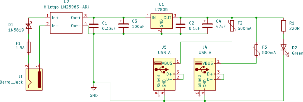
In the upcoming sections we will first talk about USB specifications, and then we will discuss a few key parts of this circuit:
- Converting 9V to 5V
- Circuit Protection
Pedal Board USB Power Delivery
When adding USB ports to a guitar pedal power supply, we need to consider how USB devices negotiate power. Simply providing 5V on the power pins isn’t enough, modern devices check the data lines (D+ and D-) to determine how much current they’re allowed to draw.
USB devices follow specific protocols to determine safe current limits:
Standard USB Data Port:
- Devices start at 100mA (safe default)
- Enumerate with host to request up to 500mA
- Requires a USB host controller (not present in our design)
USB Battery Charging 1.2 (Dedicated Charging Port – DCP):
- D+ and D- shorted together
- Signals to device: “This is a charger, draw what you need”
- Devices can request up to 1.5A per spec
- No data capability, charging only
- Simple to implement, no active components required
The Current Limiting Problem
Here’s where things get complicated. By implementing DCP mode, technically, we’re telling devices they can draw up to 1.5A. But our design is constrained by the current limits of the pedal power supply:
- My pedal board power supply: 500mA max per output
- Some higher-end supplies: 1A per output
- With current doubler adapter: 1A (uses two outputs)
In the Circuit Protection section below, we will talk about how we set the limits in the circuit. For now, it is just important to know that we are not meeting the USB 1.2 standard. Our circuit will make sure we don’t pull too much current. We will just need to be careful what we plug in. Otherwise, devices that we plug in may not work.
9V Conversion
Now that we understand the USB specification, let’s discuss the circuit. I initially started by thinking about the 9V to 5V conversion. There are two ways that we can convert the voltage: linear regulators and buck converters.
Linear Regulator
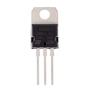
The simplest option is a linear regulator, which simply gets rid of the excess voltage as heat. Hence the reason it has a heatsink at the top.
The benefit of a linear regulator is that it is simple and it is low noise. The downside is it is not very efficient. Theoretically, we waste 4V (or 4V x 500mA = 2W) as heat. More on the “theoretical” point later.
Buck Converter
The alternative is the buck converter. The buck converter is much more complicated. The buck converter works by turning on and off the circuit very fast to achieve the target voltage. For example, if you have 9V and want 4.5V (for math simplicity), then you would turn the circuit off half the time on average. Obviously, it doesn’t work if you run it for 1 second and then turn it off for 1 second, you need it to happen so fast that the downstream circuitry doesn’t even know it happened.
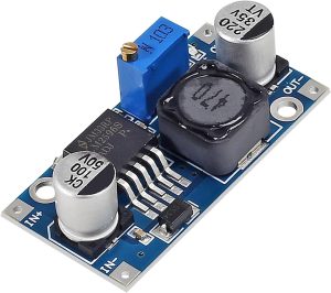
The buck converter is much more efficient than the linear regulator. We don’t waste (as much) energy since we are turning off the circuit when we don’t need it. The downside is the converter is very noisy. Without more components, if you looked at the output over a very small timescale, you would see the voltage turning on and off. Any extra noise that we create, our amp is sure to pick up.
Choosing Both: Linear Regulator + Buck Converter
For this design, I chose to combine both the buck converter and linear regulator. My intent with this approach was to efficiently convert the voltage (theoretically, this also gives me more current capacity) with the buck converter and then feed it into the linear regulator to keep the signal clean.
For the buck converter, I am using the HiLetgo LM-2596S-ADJ power module. The linear regulator is TO-220. It is important to note that for the linear regulator to work, it needs ~2V above the output voltage. Therefore, we will use the buck convert to step down the voltage from 9V to 7V and the linear regulator from 7V to 5V. If I were to do this again, I would just use the linear regulator, because I am only saving 2V minus the operation of the LM-2596. In addition, I also did not take into account the voltage drop from my protection diode (~0.4V)
I added capacitors before and after the linear regulator to control noise. The ceramic/film capacitors handle high frequencies and the electrolytic capacitors handle low frequencies (as well as voltage dips).
Circuit Protection
The second area that I considered for this circuit was how to protect the circuit. I will be plugging this into a pedal power supply (presumably with other pedals) as well as a Raspberry pico (or potentially other USB devices like my phone). Therefore, I do not want either the USB devices or my power supply to burn. Therefore, I added a few precautions.
Over Voltage
Guitar pedals can have a range of different voltages. Most require 9V. However, there are some that require 18V or even 24V. Therefore, we want to ensure that if anyone plugs in a higher voltage we are still protected. In our case, this is the benefit of our double coverage with both the buck converter and linear regulator. The buck converter can take input up to 40V, and the linear regulator can take 35V. Not that you see many 24V pedals any more, it still means we can plug in 24V and we should be fine.
Reverse Polarity
Next, guitar pedals are center pin negative. We need a way to protect against someone plugging in a center pin positive DC power jack. I added a diode, 1N5819, to protect against reverse polarity.
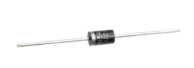
As a quick aside, I had always heard that it was Boss’ fault that pedals were center pin negative. However, the reason was much more interesting than I expected. Yes, it started with Boss, but it was because when they introduced their compact pedals in the 1970s, they needed a way to easily disconnect from a battery when the pedal was plugged into the wall. Here is a post with more info on how the switching works.
Over Current
We also want to protect against too much current. I added a fuse holder and a 1.5A fast blow fuse. Although, I briefly debated using 1A instead. I have two USB jacks which should provide up to 500mA each. Therefore, 1A would be right at the limit. But, I decided to give a little extra room with 1.5A. This might only be theoretical since, as discussed above, my pedal power supply may not provide that much current. Note that exceeding current from your pedal power supply may have undefined results. Hopefully, it just stops working. Be careful how much current you pull.
Finally, I added a 500mA polyfuse on each USB port. The polyfuse works differently than a glass fuse. When current exceeds the limit, the polyfuse heats up until it stops working. Once the fuse cools down, it can begin working again. This is convenient, because it means that you do not need to replace a fuse.

Let’s say you plug in a device that tries to draw 800mA:
- Initial connection: Device detects DCP mode (D+/D- shorted), requests high current
- Current draw starts: Polyfuse begins passing 800mA
- Fuse heats up: Internal resistance increases due to current exceeding hold rating
- Current limiting kicks in: Polyfuse resistance continues rising until current drops to safe level (~500mA)
- Device behavior: May show “slow charging” or operate at reduced performance
- Recovery: Unplug device, polyfuse cools down (~30 seconds), ready for next device
The polyfuse prevents damage but the device may not function optimally. This is a trade-off for the convenience of self-resetting protection. An alternative to a polyfuse would be an active eFuse IC like the TPS2561. These are precise and faster than a polyfuse, but are more expensive (~$1.50 versus $0.30 for a polyfuse).
Cost of the Device
So what does this cost? Here is a quick recap of the costs:
| Component | Quality | Estimated Cost (USD) |
| LM2596 Buck Converter | 1 | $1.60 |
| LM7805 Linear Voltage Regulator (TO-220) | 1 | $0.32 |
| 1N5819 Schottky Diode | 1 | $0.15 |
| 1.5A Fast-Blow Fuse | 1 | $0.30 |
| Fuse Holder | 1 | $0.29 |
| 100µF Electrolytic Capacitor | 1 | $0.10 |
| 0.1µF Ceramic Capacitor | 2 | $0.10 |
| 0.33µF Ceramic Capacitor | 1 | $0.10 |
| 500mA Polyfuse/PTC Resettable Fuse | 2 | $0.60 |
| USB Connector | 2 | $0.69 |
| DC Barrel Jack | 1 | $0.50 |
| Total: | $4.85 |
A few notes, first, this is estimated based on multiple sources. Second, for most of these components, you can’t buy just one. For example, I bought my buck converter from Amazon. The smallest quantity was 5, which cost $7.99. White the unit cost is $1.60, the real cost is $7.99. Finally, I struggled to find the polyfuses. I ultimately bought them from Digikey, which unfortunately added shipping costs as well. Therefore, my true cost was probably closer to $100. However, this gives me spare parts for future builds.

Lessons Learned
Power budget is everything. You can design the most efficient buck converter in the world, but if your pedal power supply can only provide 250mA, you’re limited by the source. Calculate your available current before you buy parts.
Simpler is better. The double-regulation scheme was overengineering. One well-designed stage (buck converter with adequate filtering) beats two mediocre stages every time.
Test before you assume. I added the linear regulator because I assumed the buck converter would be too noisy. After building and measuring, the buck converter alone produced cleaner power than I needed. Measure, don’t guess.
Conclusion
In future posts, we will jump into some uses for this USB power supply. This enables unlimited Raspberry Pico projects.
With respect to this project, although I am happy with the device, if I were to do this again, there are some changes that I would make. I would probably use either the LM2596 buck converter or the L7805 linear regulator, but not both. The efficiency gains and noise loss were minimal. Having both added unnecessary cost and required space on the PCB. I would probably choose the linear regulator for cost and very small footprint. I would also likely consider only using one USB port given the current limitations of the pedal power supply. Know your pedal supply’s limits before you build.
Would I build it again? Yes, but with the simplified design.
If you enjoyed this post, consider subscribing to the newsletter. I share work-in-progress updates, upcoming tutorials, and the occasional behind-the-scenes look at what I’m building.