In a future post, I will do a deeper dive into geometry nodes. However, I had a specific need to create an exploding object using fracture geometry nodes. I found some videos, but nothing that gave a quick description that I could read. Therefore, I created this post.
Fracture the Mesh
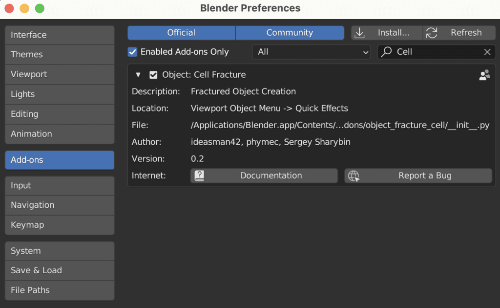
First, we will start off by using the cell fracture add-on. Go to Edit->Preferences->Add-ons and search for Cell Fracture.
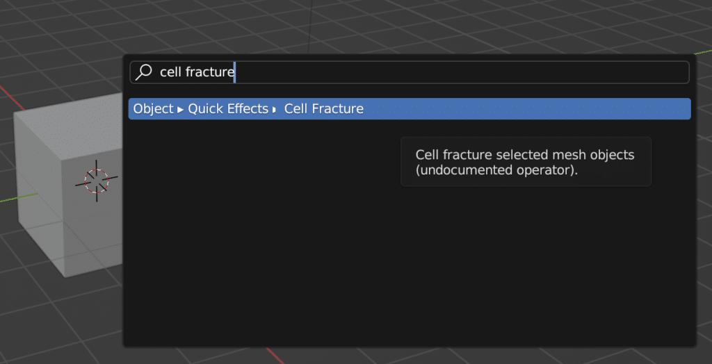
With the cube selected, press the spacebar to bring up the operator search. Type “cell fracture”.
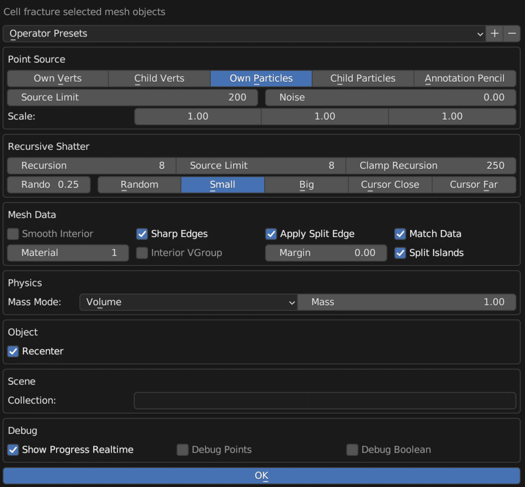
In the pop-up set the following options (feel free to play with these):
- Recursion (number of times to run the fracture simulation): 8
- Source Limit: 200
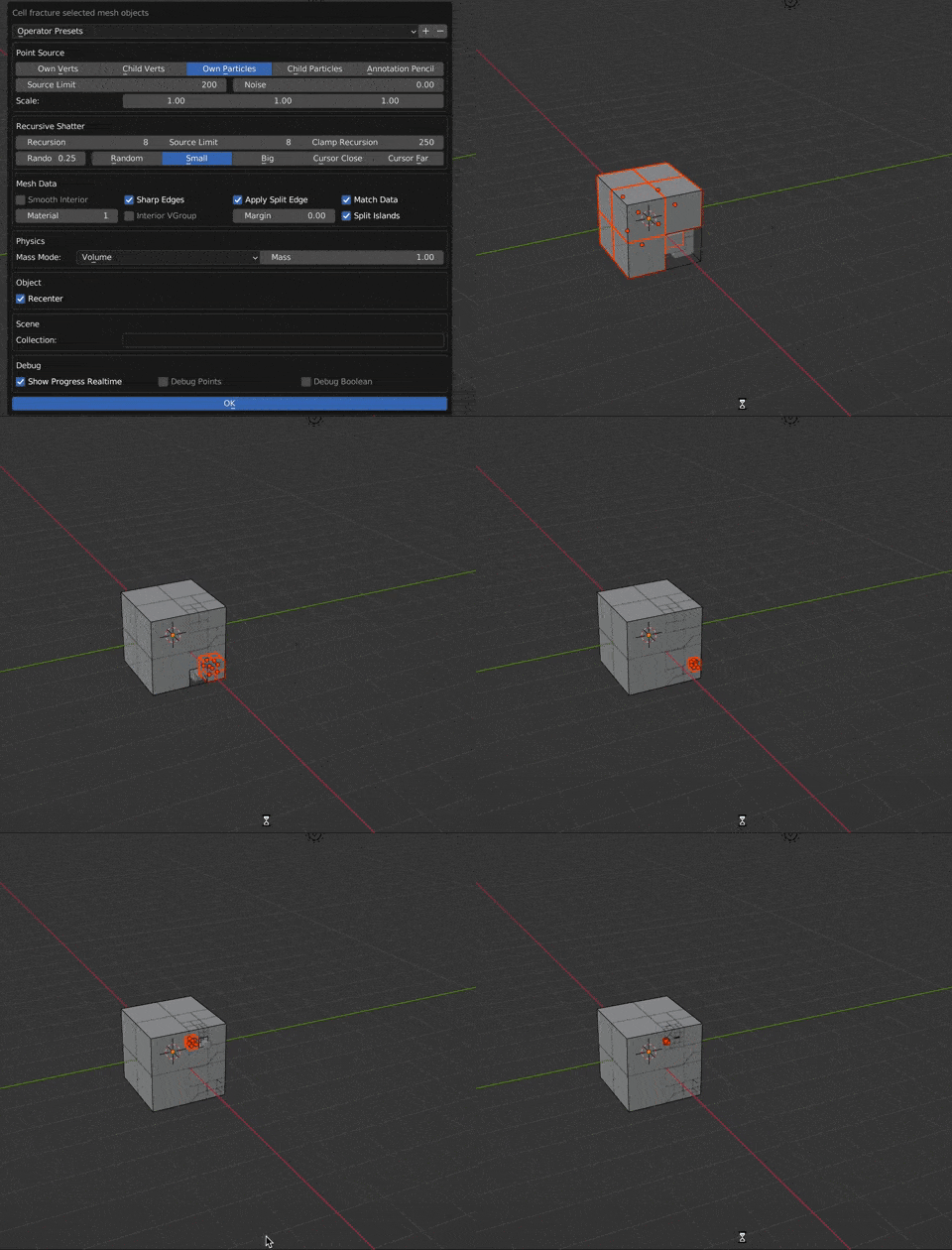
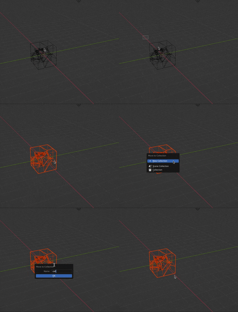
Hide the original cube. We will not need this. Next, select all of the cells. I like to use wireframe (press z->6) and then box select (press b and select the cells). Now move these into a new collection (press m->new collection). I named the collection “cells”. Hide this collection.
Setting Up the Geometry Nodes
Next, add a plane. We will use this for the geometry nodes. With the plane selected, head to the Geometry Nodes tab. Click new to add the geometry node modifier.
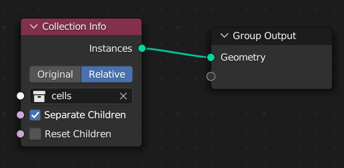
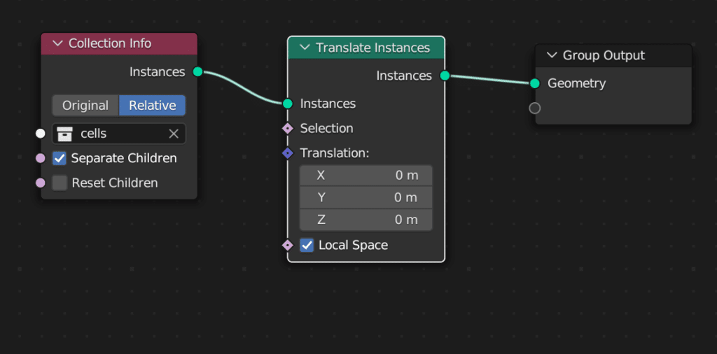
Add a Collection Info node. Connect to the group output. Set to “Relative”. Select the “cells” collection and click “Separate Children”. This allows us to treat each object in the collection as a separate instance that we can move around.
Next, add a Translate Instances node. Insert between the collection info node and the group output. The translate instances node controls the position of each node.
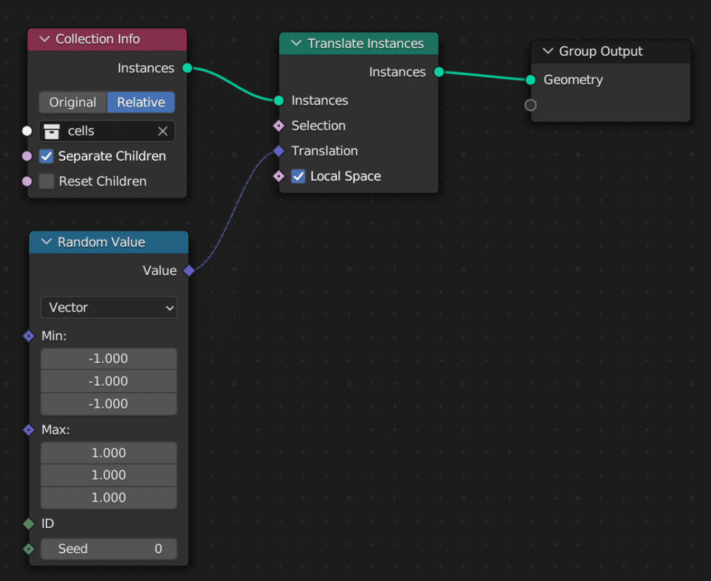
Next, add a Random Value node. Set the type to vector, the min values to -1 and the max values to 1. Connect to the Translation input of the Translate Instances node. This will generate a random vector with values somewhere between -1 and 1. Ensure that you use the vector setting. I spent a long time debugging when I used a float value instead of vector. The random values were along a diagonal because the random value assigned the same translation to all three directions (e.g., (-1,-1,-1)).
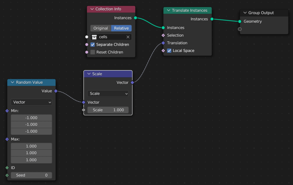
Now, add a Vector Math node between the random value and Translate Instances. Change the type to scale. This node multiples a scalar by the random vector.
Finally, we will add an input node. Press n to bring up the n panel. Click the group tab and under “Inputs” press the plus button to add an input. Name this scale. This allows you to edit from the modifier panel. We will animate this value. Alternatively, you could use a value input.
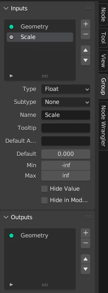
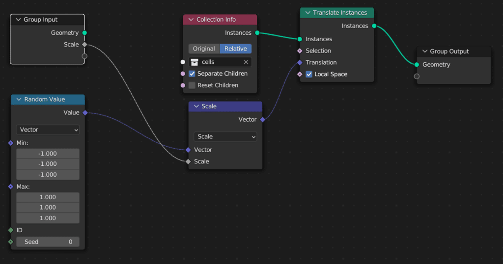
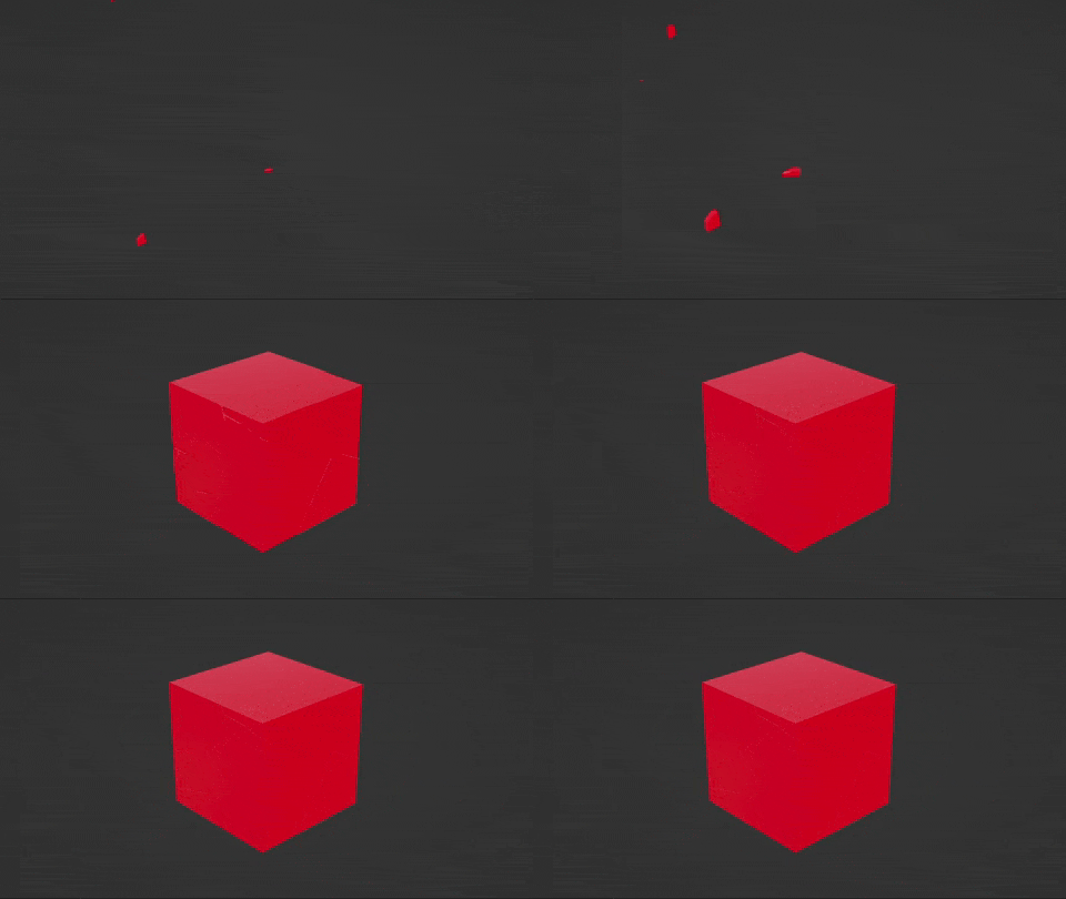
Connect this into the scale node. Now we can animate the modifier from 100 to 0 with this result.
Conclusion
This post provides a quick way to use geometry nodes with cell fracture. In future posts we will be diving into geometry nodes in more detail. We welcome any comments or suggestions below. If you found this post helpful, leave a like.


