

My son received his first Snap Circuit set when he was eight. The concept was great. Snap Circuits are an introductory electrical circuit kit that provides basic electrical components in a format that is easy for kids to use. The electrical components simply snap together, hence the name Snap Circuits. Included with the set is a manual that provides a large number of interesting projects that can be created by different configurations of the components. You simply snap the various pieces together to create an amusing circuit.
It brought back memories. When I was younger, I had something similar. You would connect wires together to create various projects. One project allowed you to send AM signals to a nearby radio.
As an adult, I felt a little frustrated by Snap Circuits. Aside from 15 pages of high level explanation, the manual did not explain why the pieces needed to be connected in a particular order. Whenever I tried to make my own circuit, I was unsuccessful. In addition, the manual includes a page of do’s and don’ts that made me feel nervous about my son even using Snap Circuits (or me trying to create my own circuits). It shows a picture of a complex circuit with giant warning images and the words “NEVER DO!”
So, in this post as well as future posts, I wanted to provide an introduction and explanation to some of the components and the circuits. Once I had additional context for the components, I found Snap Circuits to be fun (and, in some cases, easier to work with than a breadboard).
Optional: But You Need a Multimeter
Before getting started, I think everyone needs a multimeter. It is really valuable for learning electronics, but also for normal home repairs. Does this outlet have power? Recently, the multimeter saved me a lot of time and frustration finding broken Christmas lights. Most multimeters can measure voltage, resistance, and current. The multimeter I have is not very expensive and has been very helpful.
Although I haven’t tried this yet, you can also create plugs for the multimeter that can be snapped into the snap circuit.
The Basic Math: Ohm’s Law
There is some math involved, but if you can multiply, divide, and are ok working with decimals, you will be fine. The first equation that we are going to look at is Ohm’s Law. The equation is:
\( V = I * R \)In this equation:
V is voltage (measured in volts denoted by a capital V)
I is current (measured in amps denoted by a capital A)
R is resistance (measured in ohms denoted by the symbol Ω)
With this equation, it is easy to start making your own circuits. As long as you know any two factors, you can calculate the third. For example, if you have a component that needs a certain current and you know the voltage of your battery, you simply calculate R = V / I to determine how much resistance to add. This is really useful if you have a integrated circuit (IC) that cannot receive too much current.
The Warnings
As I mentioned, the warnings in the book seemed scary. I was unsure whether my son should even use the Snap Circuits since I didn’t completely understand the warning. It felt like he could make a simple wrong connection and it would end in the house burning to the ground. What I didn’t consider is that this warning is actually a learning opportunity for a concept that can help to understand circuits. The purpose of the warning in the book is to keep you from creating a short circuit. A short circuit is simply a circuit that has little to no resistance.
Why does this cause the risk of fire?
The reason that this causes the risk of fire (or injury if we are talking about the voltages in home electricity) goes back to the equation above: V = I * R
If I rearrange the equation to I = V / R. Now, if we have a voltage of 4.5V and our resistance is almost 0, let’s say 0.1, our current (I) is 45A. Theoretically, a circuit with no resistance would have an infinite current.
Going mathy lim as R approaches 0, I tends toward infinity
\( lim_{R \to 0} V / R = \infty \)Practically speaking, wires have a small amount of resistance, which means that the current is large but not infinite. In the case of Snap Circuits, I measured the connectors to have a resistance of 0.2 Ω, which would result in a current of 22A (if we assumed the battery had no internal resistance). At this point while writing, I became distracted watching YouTube videos of short circuit fires.
All of this shows that while a short is something to be aware of, don’t let it stop you from experimenting. To limit your risk, just ensure there is some load on the circuit (even just one resistor or an LED). Second, probably best not to leave your circuit connected to the batteries when you are done (just in case).

Resistance is Not Futile, Resistance is Necessary
The first component necessary to control voltage and current is the resistor. The resistor resists the flow of electricity. This resistance can be used to control the flow of electricity in a couple of ways.
First, we can use a resistor to decrease the current. The best example is if I have a 3 volt battery, and I want to light an LED using just 20 mA of current, then I need a resistor to decrease the current. How much resistance is determined by Ohm’s law. V = I*R can be re-written as R = V / I, which means that the units of resistance are volts per ampere, also called Ohms. In this equation, if I have voltage of 3V, and I want a current (I) of 0.002A, 3 / 0.002 = 150. I need resistance of at least 150Ω.
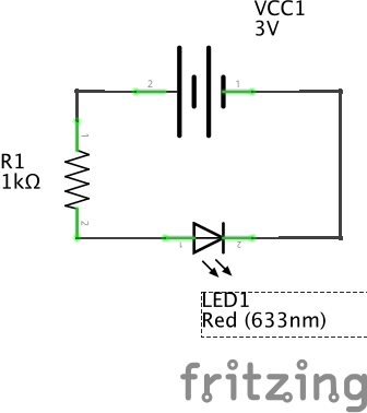
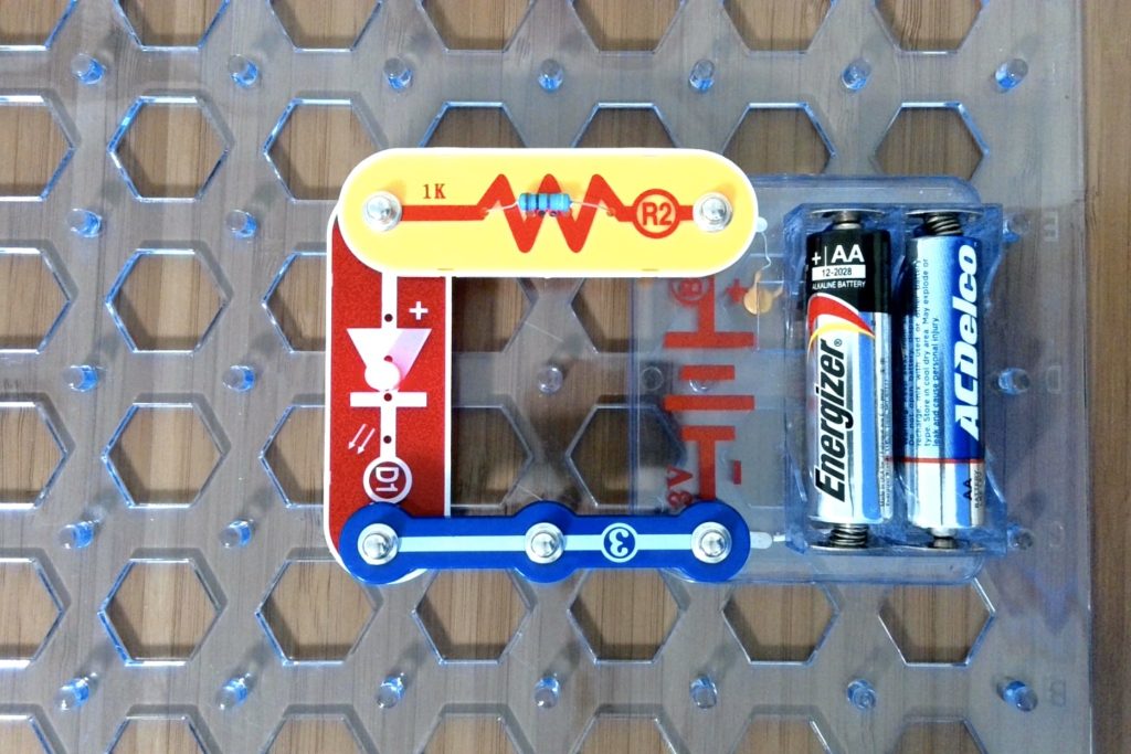
In the case of the image above, I used a 1K Ω resistor. You can always use more resistance, but not less (in the LED, more resistance just results in a dimmer LED). Despite the short circuit warnings in the book, I actually did not even need the 150Ω resistor, because some Snap Circuit LEDS have a built in resistor that protects the LED from too much current (my LED has approximately a 220Ω resistor). This built in resistor caused me initial headaches because my multimeter voltage readings did not come out as calculated until I realized the resistor existed and I started including it in the calculation.

Second, we can use resistors to change the voltage. If we have voltage that is too high for a particular component, we can add resistors before and after the component to divide the voltage. How much it divides is determined by the ratio of the resistors to the sum of all of the resistors. For example, to simply divide a voltage in half, I can use two resistors of equal value. In the image to the right (courtesy of Wikipedia), R1 and R2 would be equal size resistors.
If I want one circuit that is 10 times the other circuit, I simply use one resistor that is 10 times the other. In this case, I would use a 100 Ω resistor and a 1000 Ω resistor. With input voltage of 3V, the 100 Ω circuit is 0.27V while the 1000 Ω circuit is 2.7V.
The ability to divide voltage is really important when working with components that require a lower voltage than the input voltage.
What is Your Capacity?
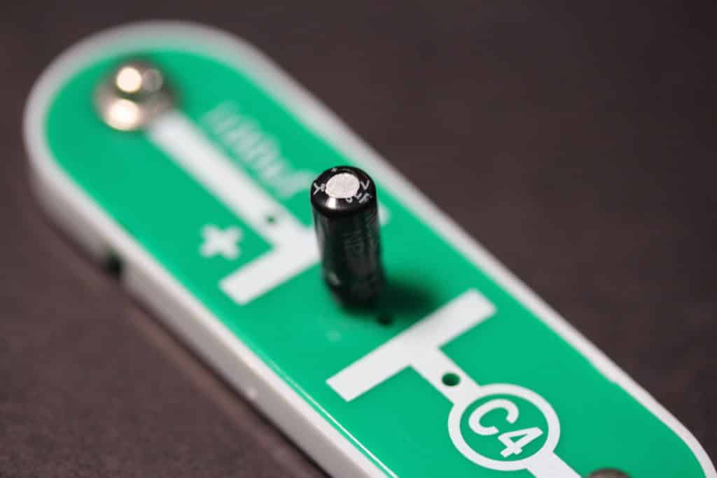
The next component that is critical to learn is the capacitor. The capacitor is like a very small battery. You can find a lot of explanations around the physics that make a capacitor work, but I really struggled to understand why you would use a capacitor (and how to actually use a capacitor). The charge held by the capacitor seemed too small to be useful. What was most confusing is that when a capacitor is fully charged, the current stops flowing through the capacitor. When I tried to use in Snap Circuits, it charged and discharged so quickly that I saw no effect. I was missing two key pieces of information. First, if you are using the capacitor as a battery, you need to place the capacitor in parallel instead of in series. That way, the electricity will still flow once the capacitor is charged. Second, you need resistance to slow the charge and discharge of the capacitor.
A capacitor works by storing charge. It is important to know that while the capacitor is storing charge, current flows. However, as soon as the capacitor is fully charged, the voltage drops to 0 and the current stops flowing. You can determine the amount of charge that a capacitor can hold by the equation Q = CV. Q is the charge, C is the capacitance (in Farads or F), and V is voltage. The amount of time it takes to charge the capacitor is 5*R*C where R is the resistance of the circuit. Therefore, by increasing the resistance or the capacitor, you can increase the amount of time that the capacitor charges and discharges.
The best example of a capacitor as a battery in Snap Circuits is the following circuit (Project 152 in the Snap Circuits Light set).
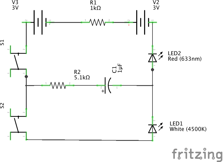
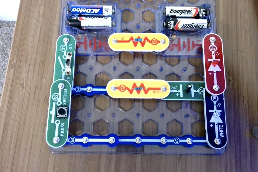
In this example, when switch S1 is turned on, current flows across R2 and the capacitor C1 until the capacitor is fully charged. LED2 will be lit while the capacitor is charging. Once the capacitor is charged, you can turn off S1 and turn on S2. This causes current to flow from the capacitor across LED1 until the capacitor is fully discharged.
Conclusion
This is just a quick overview of resistors, LEDs, and capacitors. Hopefully, with this background you can feel more confident making a few basic circuits. In future posts, we will cover more components (e.g., the transistor and some of the Snap Circuit integrated circuits (IC)). In addition, we will analyze some of the circuits in the book to understand why they work.